Injection Molded Plastic Part Design Guidelines

Recent Posts

Aerospace Plastic Injection Molding Considerations: What Sets These Programs Apart

Automotive Plastic Injection Molding Requirements: What Manufacturers Need to Know

Extrusion Blow Molding for Large Hollow Parts: How the Process Produces Larger, Complex Hollow Parts

Injection Blow Molding Process: A Closer Look at the Precision Blow Molding Process

Good part design can reduce tooling costs, improve part quality, shorten production cycles, and help prevent manufacturing issues. Below are some of the most important design considerations when developing parts for injection molding.

1. Maintain Uniform Wall Thickness

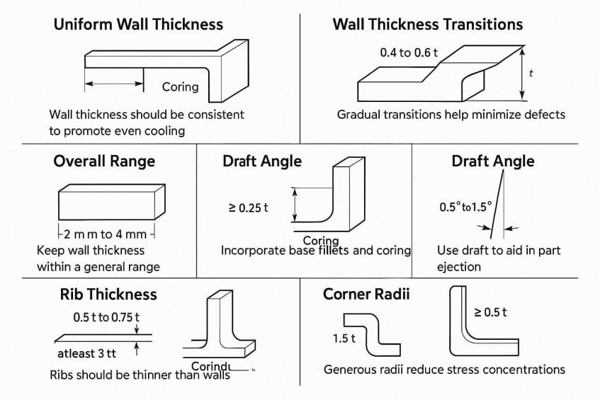
Keeping wall thickness as consistent as possible helps plastic flow evenly through the mold and reduces the risk of defects such as sink marks, warpage, and voids.

Recommended:

Avoid:
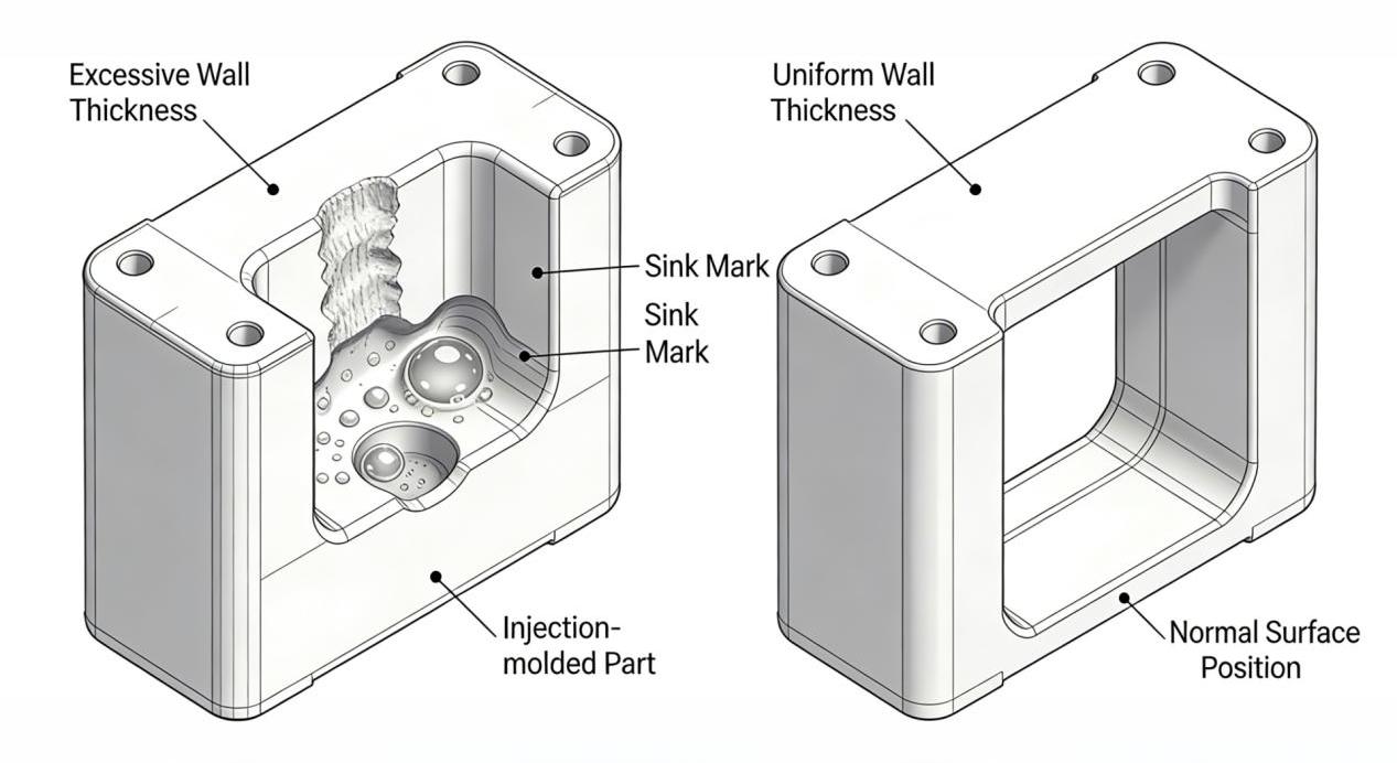
  • Use consistent wall thickness throughout the part.
  • Transition gradually between thick and thin sections.
  • Follow material-specific wall thickness recommendations.
  • Large variations in wall thickness.
  • Heavy sections that can cause sink marks or long cooling times.
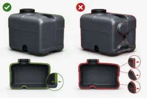
Injection molded plastic part design guidelines comparing excessive and uniform wall thickness to prevent sink marks
Injection molded plastic part design guidelines comparing rounded corners and reinforced bosses with defect-prone designs

2. Add Draft Angles

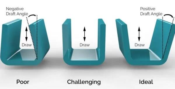
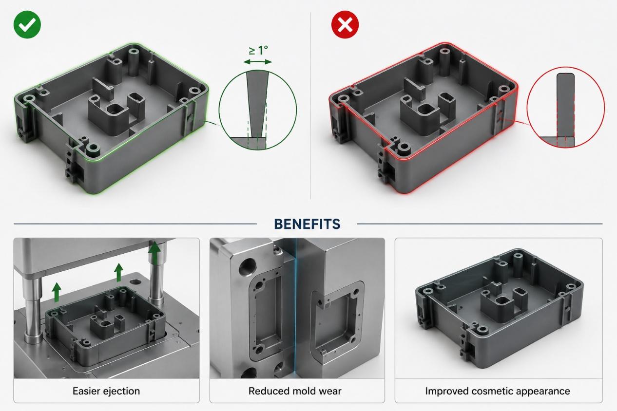
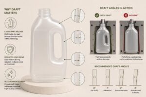
Draft angles allow molded parts to release more easily from the mold, reducing drag marks and part damage during ejection.

Recommended:

Benefits:

  • Minimum 1° draft per side.
  • Increase draft for textured surfaces.
  • Add draft to all vertical walls.
  • Easier ejection.
  • Reduced mold wear.
  • Improved cosmetic appearance.
Injection molded plastic part design guidelines showing correct draft angles for walls, ribs, and cylindrical bosses
Injection molded plastic part design guidelines showing how draft angles improve ejection, mold wear, and appearance

3. Use Ribs Instead of Thick Walls

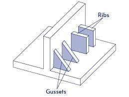
Ribs provide strength and stiffness without significantly increasing wall thickness.

Recommended:

Benefits:
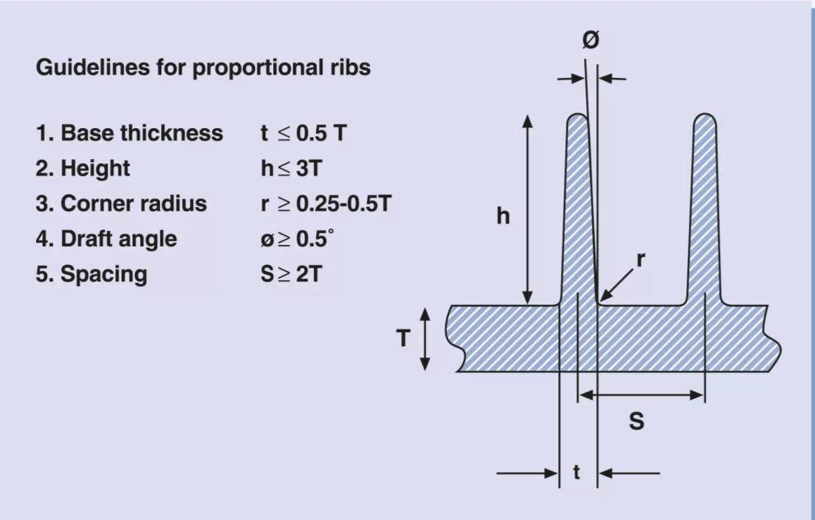
  • Rib thickness: 50–60% of nominal wall thickness.
  • Add draft to rib walls.
  • Use multiple ribs rather than one large rib.
  • Increased rigidity.
  • Reduced material usage.
  • Less risk of sink marks.
Injection molded plastic part design guidelines for rib thickness, height, radius, draft angle, and spacing
Injection molded plastic part design guidelines illustrating ribs and gussets used for structural reinforcement

4. Design Proper Corner Radii

Sharp corners create stress concentrations and can impede material flow.

Recommended:

Benefits:
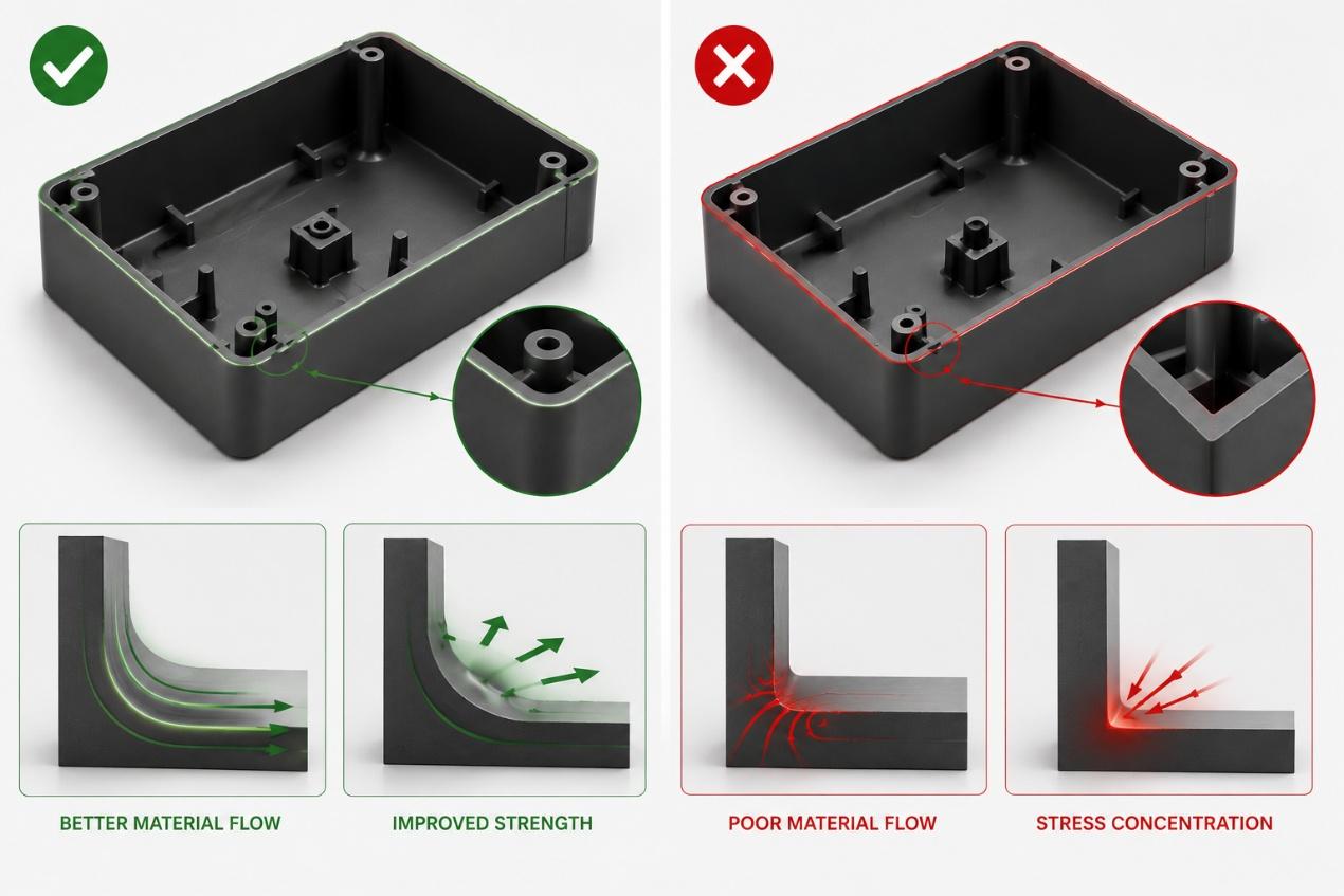
  • Use inside radii whenever possible.
  • Radius should typically be at least 25–50% of wall thickness.
  • Maintain smooth transitions between features.
  • Better material flow.
  • Improved strength.
  • Reduced stress cracking.
Injection molded plastic part design guidelines comparing rounded and sharp corners for material flow and stress reduction

5. Optimize Boss Design

Bosses are commonly used for screws, inserts, and assembly features.

Recommended:

Benefits:
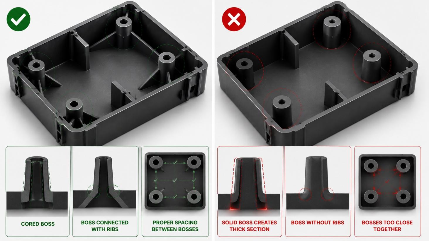
  • Core out bosses to avoid thick sections.
  • Connect bosses to nearby walls using ribs when possible.
  • Maintain proper spacing between bosses.
  • Reduced sink marks.
  • Better dimensional stability.
  • Improved assembly performance.
Injection molded plastic part design guidelines comparing cored and solid bosses, rib support, and proper boss spacing

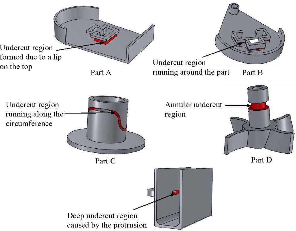
6. Avoid Undercuts When Possible

Undercuts increase tooling complexity and often require slides, lifters, or secondary operations.

Recommended:

Benefits:
  • Simplify geometry when possible.
  • Design features that can be molded in the tool opening direction.
  • Evaluate whether an undercut is truly necessary.
  • Lower tooling costs.
  • Faster mold cycles.
  • Simpler mold maintenance.
Injection molded plastic part design guidelines showing undercut regions caused by lips, protrusions, and annular features

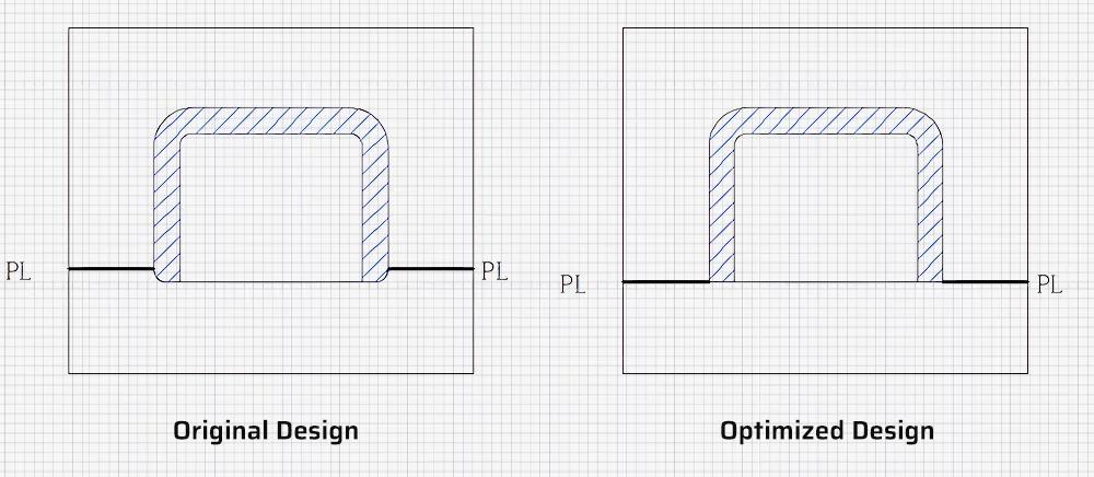
7. Consider Parting Line Location

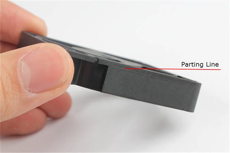
The parting line is where the mold halves separate.

Recommended:
  • Place parting lines in less visible areas.
  • Avoid critical sealing surfaces.
  • Consider moldability early in the design stage.
Injection molded plastic part design guidelines comparing original and optimized parting line placement
Injection molded plastic part design guidelines showing a visible parting line on a finished molded component

Get started

Start Your Next project with Hi-REL Plastics & Molding