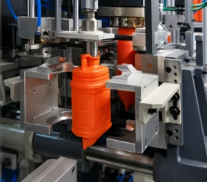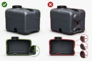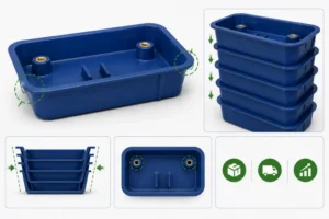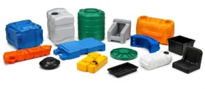
Injection mold tooling engineering part quality outcomes are determined before a single shot of plastic is ever injected. The mold determines the shape, surface, dimensions, and functional features of every part produced throughout its service life — and the quality, durability, and design of that mold determines whether production is efficient and consistent or plagued by dimensional variation, excessive scrap, and premature tool failure. Understanding injection mold tooling in depth — not just as a procurement line item but as the engineering system it is — equips product developers, engineers, and procurement professionals to make better tooling investment decisions, communicate more effectively with tooling suppliers, and set realistic expectations for program timelines and costs.
Tooling decisions made early in a product development program have consequences that extend across the entire production lifecycle. A mold designed and built with appropriate care for the application’s requirements — material, volume, tolerances, and regulatory context — becomes a reliable production asset that pays its cost back over thousands or millions of cycles. A mold designed too cheaply, too quickly, or without genuine understanding of the application’s demands becomes a recurring source of quality issues, unplanned maintenance costs, and schedule disruptions. This article examines the engineering, economics, and quality considerations that define injection mold tooling engineering part quality outcomes across the range of programs and industries that injection molding serves. Explore Hi-Rel’s precision tooling capabilities to see how these principles translate into production results.
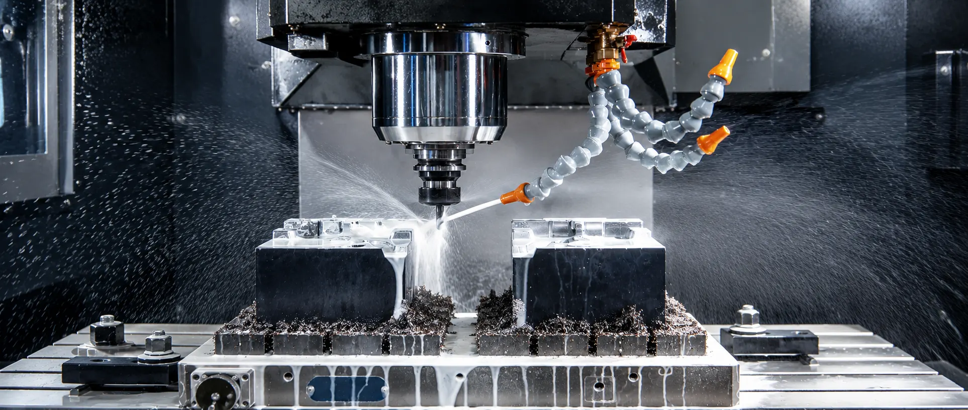
An injection mold is a precision assembly of multiple functional systems that must work together reliably under the thermal, pressure, and mechanical cycling of injection molding production. The cavity and core — the machined steel surfaces that define the part’s external and internal geometry, respectively — are the most visible elements, but they depend entirely on the surrounding systems for their performance. The mold base provides the structural framework that houses and supports the cavity, core, and all other systems. Guide pins and bushings align the two mold halves with the precision required for the part’s parting line to meet without flash or misalignment. The sprue bushing accepts the injection machine nozzle and channels melt into the runner system.
The runner system distributes melt from the sprue to the gates — the entry points into each cavity. In cold runner systems, the runners solidify with each cycle and must be removed as a separate piece from the part; in hot runner systems, heated manifolds and drops maintain the material in a molten state between cycles, eliminating runner waste. The cooling system — channels machined through the mold body — circulates temperature-controlled water to extract heat from the solidifying plastic and maintain consistent mold temperature cycle to cycle. The ejection system — typically a plate equipped with ejector pins, blades, or sleeves — strips the solidified part from the core when the mold opens. Each of these systems must be designed, built, and maintained to the tolerances and performance levels appropriate for the specific program, because the interaction of all these systems collectively determines injection mold tooling engineering part quality outcomes.
The choice of steel for mold construction is one of the most consequential decisions in tool design, affecting tool life, surface capability, machinability, weld repairability, and total cost over the production program. Pre-hardened P20 tool steel is the most widely used mold material for general-purpose injection molding applications. P20 is supplied in a hardened condition that eliminates the need for post-machining heat treatment, reducing tooling lead time and the risk of distortion during hardening. It machines well, polishes to moderate surface quality, and is readily weld-repaired. P20 molds are appropriate for most commercial, industrial, and moderate-volume production applications where the resin is not highly abrasive.
H13 hot-work tool steel, hardened to higher Rockwell hardness levels, suits high-volume production molds. It also handles abrasive glass-filled and mineral-filled resins that can quickly wear softer steels. H13 provides greater wear resistance than P20. It supports longer intervals between cavity refurbishment and maintains dimensional consistency across higher cycle counts. Stainless steels, particularly 420 and 440C grades, suit medical device and pharmaceutical tooling. These steels provide corrosion resistance in cleanroom environments. They also help maintain smooth, defect-free cavity surfaces throughout production. Aluminum molds offer a different balance of cost and durability. They require less initial investment but provide lower cycle life than steel. This tradeoff works well for development tooling, bridge programs, and lower-volume production. Steel selection plays a foundational role in injection mold tooling engineering part quality outcomes. It determines whether a tool can consistently produce conforming parts throughout production. Engineers should discuss these tradeoffs with tooling suppliers early in the program.
Contact Hi-Rel to discuss the right tooling strategy for your application.
The gate — the point at which molten plastic enters the mold cavity from the runner system — is one of the most consequential design elements in determining injection mold tooling engineering part quality outcomes. Gate type, size, and location collectively determine how the cavity fills, where weld lines form, what the gate vestige looks like on the finished part, and how easily the gate can be removed or trimmed. A well-designed gate produces a part that fills completely and uniformly, with weld lines in non-critical locations and a gate vestige that meets the part’s appearance or functional requirements. A poorly located or sized gate produces short shots, excessive weld line weakness, unacceptable surface marks, or difficult trimming — problems that are expensive to correct after the mold is built.
Gate type selection depends on the application’s requirements. Edge gates are simple to machine and easy to trim but leave a visible vestige on the part’s parting line surface. Submarine (tunnel) gates enter the cavity below the parting line and shear automatically during ejection, eliminating the gate trimming step — but they require more complex mold machining and are not suitable for all materials. Hot tip gates and valve gates — used in hot runner mold systems — leave minimal vestiges and allow precise control of gate opening and closing, making them preferred for appearance-critical parts and for multi-cavity molds where balanced fill is important. Fan gates and film gates are used for thin-wall parts and flat panels where a wide, low-pressure gate entry reduces orientation effects and improves dimensional stability across the part width.
Cooling system design is the single tooling element with the largest potential impact on production economics and injection mold tooling engineering part quality outcomes. And cooling time — the period during which the part solidifies in the mold before it can be safely ejected — typically accounts for 50 to 70 percent of the total cycle time. Every second of cooling time reduction translates directly into higher production throughput per press hour and lower per-part manufacturing cost. The investment in more effective cooling during tool design — whether through better channel placement, conformal cooling geometries, or thermally optimized insert materials — pays back in production economics over the life of the program.
Conventional cooling channels use straight drilled paths through the mold body. Mold geometry limits how closely these channels can approach the cavity surface. This limitation can leave some areas with inadequate cooling. Conventional channels cannot closely follow complex curved cavity surfaces. As a result, they may create uneven thermal conditions across the mold. Conformal cooling uses channels that follow the part surface at a consistent distance. Additive manufacturing produces these channels and allows more uniform heat extraction across complex geometries. In challenging applications, this approach can reduce cycle times by 20 to 40 percent.
However, additive-manufactured conformal cooling inserts cost significantly more than conventional cooling systems. High-volume programs can justify this investment because even small cycle time improvements can create substantial cumulative savings.
The number of mold cavities directly determines parts produced per cycle. It also helps manage the economics of high-volume production. Single-cavity molds suit development programs, low-volume production, and complex parts. These parts can be difficult to balance in multi-cavity configurations. As production volume increases, adding cavities can improve economics. The additional tooling cost spreads across more parts per cycle. This reduces the machine cost per part. The crossover point depends on several factors. These include machine time, volume forecasts, and the cost difference between single- and multi-cavity tooling. This point determines when additional tooling investment becomes worthwhile.
Cavity balance ensures that all cavities fill at consistent rates and pack pressures. It remains a central technical challenge in multi-cavity tooling. It also affects injection mold tooling engineering part quality outcomes. Imbalanced filling can create differences in dimensions, surface quality, and mechanical properties. These differences can increase sorting challenges and overall scrap rates. Naturally balanced runners offer a reliable approach for standard cavity counts. They position each cavity at an equal distance from the sprue. They also use geometrically identical flow paths. Manufacturers use artificially balanced runners when natural balance is not possible. However, these systems require more careful design and process validation. This helps confirm consistent balance across the operating process window.
Tooling for medical device, pharmaceutical, and aerospace manufacturing requires formal qualification before production use. This process plays a central role in injection mold tooling engineering part quality outcomes in regulated markets. The qualification protocol includes Installation Qualification, Operational Qualification, and Performance Qualification (IQ/OQ/PQ). It provides documented evidence that the team installed the mold correctly. It also confirms that the mold operates within defined parameters and consistently produces parts that meet drawing requirements. This documentation becomes part of the device’s design history file for medical applications and is subject to review during FDA inspections and customer quality audits.
Mold qualification in regulated contexts requires planning that begins during tool design — not after the mold is built. Critical characteristics must be identified and their measurement methods defined. Sampling plans for OQ and PQ studies must match the required confidence level. They must also meet the applicable regulatory framework. Teams must validate process parameter ranges established during OQ with PQ data. The data should cover the edges of those ranges, not just nominal conditions. Teams must evaluate any mold modification against the qualified state. These changes may include cavity repairs, gate adjustments, or cooling system changes. Modified tools may require partial or full requalification before returning to production.
ISO 13485 standards govern the quality management framework within which this qualification work occurs. The discipline required to manage qualification in regulated industries is one of the clearest differentiators between suppliers with genuine regulated-market experience and those who have not worked within these frameworks.
Systematic preventive maintenance throughout a tool’s production life helps sustain the injection mold tooling engineering part quality outcomes the mold was designed and qualified to deliver. Maintenance includes cleaning parting line surfaces and vents, lubricating moving components, and inspecting ejector pins and bushings. Teams should replace worn components, clean water cooling channels, and periodically polish cavity surfaces. Abrasive resins and release agents can degrade these surfaces over time. Well-maintained tooling produces consistent parts that meet design specifications. Neglected tooling can cause progressive dimensional drift and surface degradation. It can eventually cause failures that interrupt production and require costly emergency repairs.
Tooling life management tracks each mold’s cycle count and maintenance history. Teams can then plan refurbishment or replacement before failures occur. Suppliers that maintain detailed records and communicate refurbishment needs early help customers plan tooling investments and avoid supply disruptions. Customers who own their tooling also benefit from maintenance transparency. They can review each mold’s history and current condition. This information helps them decide when to extend tool life, refurbish tooling, or replace it as production programs evolve.
Hi-Rel Plastics & Molding maintains in-house tooling capabilities that span design, build, qualification, and ongoing production maintenance. The company integrates tool design with production requirements. This ensures each mold matches the program’s resin, production environment, and quality requirements. Hi-Rel also brings experience with regulated industry tooling. Its medical device and aerospace work includes qualification protocol management and required documentation practices.
For customers who own their tooling, Hi-Rel maintains transparent records. The team also communicates proactively about tool condition, maintenance intervals, and anticipated refurbishment needs. For customers evaluating tooling strategies, Hi-Rel provides guidance on steel selection, cavity count, runner configuration, and cooling approaches. The team bases these recommendations on production volume, timeline, and part requirements. This practical input comes from a supplier that manages tooling throughout its production life. As a result, customers can achieve better injection mold tooling engineering part quality outcomes across the entire program lifecycle.
Injection mold tooling engineering part quality outcomes take shape most effectively during the design stage. At this stage, teams can consider material selection, part geometry, parting line location, gate type, runner configuration, cavity count, and steel grade together. Making these decisions separately can produce suboptimal results. Instead, effective tooling programs bring the part designer, mold designer, and production molding team together from the start. Hi-Rel Plastics & Molding supports this collaborative approach for its customers.
Hi-Rel Plastics & Molding welcomes engineers, product developers, and procurement professionals to discuss tooling requirements. Whether your program requires new tooling development, existing tooling evaluation, or a new supplier for production tooling, the Hi-Rel team can help. The team provides technical guidance and a realistic assessment of the best path forward.