Liquid Injection Molding Design and Defect Prevention turns a two-part liquid silicone rubber into precise, flexible parts, but it behaves very differently from thermoplastic molding. The material is thin as water when injected, it cures in a hot mold instead of cooling, and it will flow into any gap it finds. Parts that ignore these traits tend to flash, trap air, or tear on release.
This article looks at liquid injection molding from the design and troubleshooting side. It covers part design rules, parting lines, gating, venting, cure control, and the defects engineers see most often, so that teams can avoid problems before tooling is built rather than chase them afterward.
Why Liquid Injection Molding Behaves Differently from Thermoplastic Molding
In liquid injection molding, two components are metered, mixed, and pushed into a heated mold where a chemical reaction cures the material. A thermoplastic is melted and then cooled to solidify. That reversal, with a cold material delivery system and a hot mold, changes nearly every design and tooling decision.
The low viscosity of the material is both an advantage and a hazard. It fills thin walls and fine detail with little pressure, which suits small medical and electronic parts. The same property means tool surfaces must match closely, because liquid silicone material escapes through gaps that a thermoplastic would never penetrate.
Designing Parts for Liquid Injection Molding
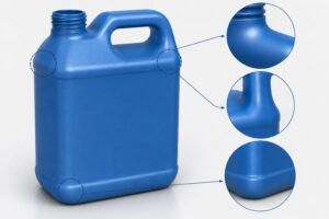
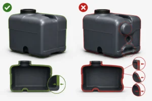
Good Liquid Injection Molding Design and Defect Prevention favors uniform wall thickness, since thick sections cure more slowly than thin ones and can distort or leave undercured areas. Where thickness must vary, transitions should be gradual. Generous radii help material flow and reduce stress at corners where silicone can tear during removal.
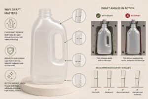
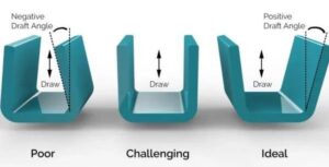
Silicone is flexible, so moderate undercuts can often be released by stretching the part, which simplifies tooling. Draft still helps, particularly on stiffer durometers. Shrinkage in liquid injection molding is predictable but not negligible, so tools are cut with an allowance that the molder refines during first-article trials.
Parting Lines and Flash Control
Flash is the most common complaint in liquid injection molding. Tool halves must close with extremely tight fit, and parting lines should be placed where a small witness mark is acceptable. Complex parting lines raise the risk of flash and the cost of tool construction.
Many programs specify a flash-free or low-flash design, which requires precise steel work and regular maintenance. Discussing the acceptable flash limit and the trimming method early lets the molder choose between a flashless tool design, cryogenic deflashing, or manual trimming based on cost and part function.
Gating and Cold Runner Design
Because the material cures with heat, a liquid injection molding tool uses a cold runner system that keeps the liquid below its cure temperature until it enters the cavity. This avoids the runner waste common in thermoplastic molding, and it keeps material cost low on high-volume programs.
Gate type and location influence fill balance, appearance, and the amount of cleanup needed. Valve gates and pin gates are common because they leave small vestiges and allow precise shutoff. In multi-cavity tools, balanced runners help every cavity fill and cure at the same rate.
Venting and Air Entrapment
Air trapped in the cavity causes voids, short fills, and burn marks. Because liquid silicone flashes through very small gaps, vents must be shallow enough to pass air without passing material. Many liquid injection molding tools use vacuum assistance to remove air before injection, which improves fill and reduces cosmetic defects.
Vent locations should follow the last areas to fill, which flow simulation can identify before steel is cut. Neglecting venting is a frequent cause of rejects and scrap, and it is much cheaper to design vents correctly than to add them after trials reveal problems.
Cure Temperature and Cycle Time in Liquid Injection Molding
Cure is controlled by mold temperature, part thickness, and material formulation. Even temperature across the tool matters because hot and cold zones cure at different rates, causing inconsistent hardness or incomplete cure. Heater placement and temperature monitoring, including thermocouples near critical features, are therefore important parts of Liquid Injection Molding Design and Defect Prevention.
Cycle time follows the thickest section of the part. Faster-curing formulations shorten cycles but narrow the processing window, so molders balance speed against the risk of premature cure in the nozzle or runner. A process window study during validation defines the temperature and time range that produces good parts consistently.
Common Defects and How to Correct Them
Typical liquid injection molding defects include flash, voids, tearing at ejection, incomplete fill, and surface blemishes. Each has characteristic causes. Flash points to tool wear or excessive clamp mismatch, voids suggest venting or air entrapment, and tearing indicates sharp corners, adhesion to the steel, or an ejection problem.
Systematic troubleshooting starts with documenting where and when a defect appears. Changes to injection speed, mold temperature, or venting are tested one at a time, and results recorded. Disciplined records make molding problems easier to solve and also support quality documentation for regulated parts.
Post-Curing and Secondary Operations
Some silicone parts require a post-cure bake. This process removes volatiles and helps stabilize material properties. Medical and food-contact applications commonly use post-curing. However, the need depends on the material, application, and customer specifications. Define post-curing requirements before validation. This helps ensure the process meets the required specifications.
Secondary steps may include trimming, inspection, cleaning, bonding, overmolding onto a substrate, and cleanroom packaging. Planning these steps with the liquid injection molding process, rather than treating them as afterthoughts, shortens lead times and reduces handling that could damage soft parts.
Why Hi-Rel Plastics Offers Liquid Injection Molding
Hi-Rel Plastics & Molding provides liquid injection molding alongside thermoplastic injection, blow, rotational, and thermoforming processes. Because the company works across several processes, its engineers can advise on whether silicone is the right material for a given application or whether another approach would serve better.
Supported by ISO 13485, ISO 9001, and cleanroom manufacturing capability, Hi-Rel can run liquid injection molding programs for medical, aerospace, and industrial customers with documented process control, lot traceability, and inspection records. Secondary operations and assembly are available under the same quality system.
Ready to Start a Liquid Injection Molding Design and Defect Prevention Project?
A productive first conversation covers the part’s function, durometer, tolerances, expected volumes, and any regulatory requirements. Sharing drawings or models early lets a molder recommend design changes while they are still inexpensive to make.
Hi-Rel Plastics & Molding welcomes inquiries from engineers and procurement professionals evaluating liquid injection molding for an upcoming program. Contact Hi-Rel Plastics & Molding to share your part requirements and discuss how Hi-Rel’s capabilities can support your project.