Custom Blow Molding Part Design produces hollow plastic parts, from bottles and jugs to ducts, tanks, and housings, by inflating heated plastic inside a mold. The process suits shapes that would be difficult or expensive to make any other way, and it scales from small runs to high-volume production. Because every container is different, early design decisions strongly influence cost, strength, and manufacturability.
This article looks at custom blow molding from the design side. It covers process selection, wall thickness, neck finishes, parting lines, resin choice, tooling, and quality checks, with the aim of helping engineers and buyers make informed decisions before a mold is cut.
What Custom Blow Molding Covers
Custom blow molding refers to hollow parts designed for a specific product rather than chosen from a stock catalog. A custom bottle may have a unique shape, capacity, neck finish, or handle, and an industrial part may have integrated features such as mounting points or ribs. The molder develops tooling around the customer’s geometry.
The work usually starts with a drawing, a sample, or a concept and moves through design review, tooling, sampling, and production. Because the tool is made for one part, Custom Blow Molding Part Design programs involve upfront investment, which makes early design review especially valuable.
Choosing Between Extrusion and Injection Blow Processes
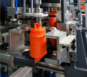
Extrusion blow molding forms a hollow tube of heated plastic, called a parison, and inflates it inside a closed mold. It handles a wide range of shapes and sizes, including handles and large containers, and tooling is relatively economical. The process leaves a pinch-off seam and trimmed flash that require attention in design.
Injection blow molding first molds a preform on a core pin, then transfers it to the blow mold. It produces precise neck finishes, no flash scrap, and consistent wall distribution, which suits smaller containers. Tooling costs more, and the process does not handle handles or large parts as readily. The right process depends on the shape, size, and volume of the part, and a molder that runs both can recommend honestly.
Wall Thickness and Blow Ratio in Custom Blow Molding
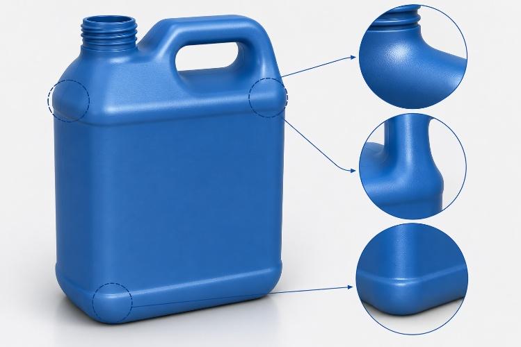
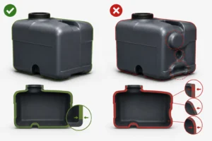
Wall thickness is the central technical issue in Custom Blow Molding Part Design. Because the plastic stretches as it inflates, areas that stretch the most become thinnest, such as corners and deep features. Thin spots can fail under load or leak, so designers aim for even distribution.
Blow ratio, the relationship between the starting diameter and the finished diameter, affects how much the material stretches. Large or deep features raise the ratio and risk thin walls. Generous radii, moderate depth, and gradual transitions help material flow into the mold evenly and improve strength. Computer simulation or test samples can confirm the thickness map before production tooling is committed.
Neck Finishes, Closures, and Threads
Containers must work with their closures, so neck finish design is critical. Industry standards define common thread profiles and dimensions, and following them ensures that caps, pumps, and seals fit reliably. A blow molding program should confirm the closure supplier’s specifications early.
In extrusion blow molding, necks are formed by compressing the plastic, and they may need trimming or calibration for tight tolerances. Injection blow molding forms necks directly in the preform, which gives better dimensional control. Sealing surfaces should be specified clearly, since leaks often trace to neck problems. Tolerances on thread diameter and sealing surface height deserve particular care.
Parting Lines, Handles, and Surface Details
The mold halves meet at a parting line that leaves a visible witness mark on the part. Placing it along a natural edge or an unobtrusive surface improves appearance. Parting line location also affects wall thickness, since material is pinched along that line in extrusion processes.
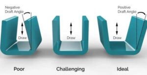
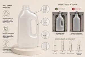
Handles, ribs, and textures add function but also complexity. Integrated handles are common in extrusion blow molding and need adequate openings and radii. Surface textures and embossed logos are possible in Custom Blow Molding Part Design but should be designed with sufficient draft and depth for clean release. Venting in the mold also influences how sharply fine details reproduce.
Resin Selection for Custom Blow Molding
High-density polyethylene is widely used in blow molding for its chemical resistance, toughness, and low cost. Polypropylene offers stiffness and higher temperature resistance, while PET gives clarity and barrier properties, and other engineering resins serve specialized parts. Choice depends on contents, environment, and regulatory needs.
Compatibility with the contents is important in blow molding. Chemicals, oils, and solvents can cause stress cracking or permeation in some resins, so testing with the actual product over time, and at elevated temperature where relevant, is wise. For food-contact uses, resin grades must meet applicable regulatory requirements. The FDA regulates substances used in food-contact materials, including packaging and containers intended to contact food.
Prototype and Production Tooling
Blow molds are typically made from aluminum or steel. Aluminum molds are less expensive and quicker to build, which suits prototypes and moderate volumes, while steel molds last longer on high-volume programs. Cooling channel design affects cycle time and part quality.
Prototype samples let teams evaluate fit, feel, and function before committing to production tooling. Some blow molding programs start with a single-cavity prototype tool and move to multi-cavity production tooling as demand grows, reusing lessons from the early samples. Cavity count is usually chosen to match the machine and annual demand.
Secondary Operations and Quality Checks
After molding, parts may need trimming, leak testing, labeling, decorating, or assembly. Planning these operations early avoids surprises, and a molder that offers them in house shortens lead time and reduces handling.
Quality checks in Custom Blow Molding Part Design include weight, wall thickness measurements, dimensional checks on necks, and leak or burst testing. Documented sampling plans and records support traceability, which is particularly important in regulated industries such as medical and aerospace.
Why Hi-Rel Plastics Offers Custom Blow Molding
Hi-Rel Plastics & Molding provides custom blow molding alongside injection, rotational, and thermoforming processes. Its engineers review part designs with customers and recommend the process and tooling approach that best fits the shape, volume, and application.
Supported by ISO 13485, ISO 9001, and AS9100D certification and cleanroom manufacturing capability, Hi-Rel can support custom blow molding programs for medical, aerospace, and industrial customers. Secondary operations and assembly are available under the same quality system.
Ready to Start a Custom Blow Molding Part Design Project?
The best time to talk with a molder is before the design is final. Sharing a sketch, sample, or drawing along with expected volumes, contents, and closure requirements lets the molder identify risks and suggest changes while they are inexpensive to make.
Hi-Rel Plastics & Molding welcomes inquiries from engineers and procurement professionals evaluating custom blow molding for an upcoming program. Contact Hi-Rel Plastics & Molding to share your part requirements and discuss how Hi-Rel’s capabilities can support your project.