What is design for manufacturability in plastic injection molding? It is the practice of shaping a part so it molds consistently, cleanly, and at a sensible cost. Design for manufacturability (DFM) reviews a part before steel is cut. It catches problems while they are still easy and cheap to fix.
We have molded plastic parts in Riverside, California, since 1984. Over 40+ years, we have seen DFM decide whether a program launches smoothly or struggles through months of rework. This guide answers the questions engineers and buyers ask most about it.
DFM is a structured review of a part design against the realities of the molding process. It looks at geometry, material, tolerances, and tooling. The goal is a part that fills, cools, ejects, and measures the same way every cycle.
A DFM review usually happens after the customer sends a 3D model and before mold design begins. We return feedback on risks and recommend changes. The design owner then decides which changes to accept.
Several roles contribute. The product designer knows the function. The toolmaker knows what steel can do. The process engineer knows how the resin behaves in the press. Quality staff know what can be measured reliably.
When these people review a part together, fewer issues surface during sampling.
DFM works best before the design is frozen. Changing a 3D model costs very little. Changing a finished mold can mean welding, re-cutting, or new inserts.
Early DFM also improves quotes. A supplier can price the right tool instead of guessing around open questions.
Most molding problems trace back to part design, not the press. Sink marks, warping, short shots, and sticking parts often start in the CAD model. DFM moves those discoveries to the cheapest point in the program.
It is meant to prevent avoidable defects, tool rework, and schedule delays. It also prevents tight tolerances where they add cost without adding function. In short, it protects quality, timeline, and budget at the same time.
DFM affects tooling cost, cycle time, scrap, and secondary operations. A uniform wall cools faster, which shortens cycles. Eliminating an undercut can remove a slide from the mold. Designing in a snap fit can remove a fastening step.
Small design choices add up across thousands or millions of parts.
The guidelines below apply to most thermoplastic parts. Exact values depend on the resin and part size, so we always confirm them during review.
Uneven walls cool at different rates. Thick sections shrink more and can cause sink marks, voids, or warp. Uniform walls fill more evenly and hold dimensions better.
When thickness must change, a gradual transition works better than a sudden step.
Draft is a slight taper on walls that lets the part release from the mold. Many parts use about 1 to 2 degrees on vertical walls. Textured surfaces need more, because the texture grips the steel.
Too little draft causes drag marks, scuffing, and ejection problems.
Sharp inside corners concentrate stress and restrict resin flow. Adding radii improves strength and filling. A common guideline sets the inside radius at about half the wall thickness or more.
Matching outside radii help keep the wall uniform through the corner.
Ribs add stiffness without thickening the whole wall. They are often sized at about 50 to 60 percent of the adjoining wall to limit sink. Bosses for screws or inserts should connect to walls with ribs or gussets, not stand as thick solid posts.
Undercuts block a part from ejecting straight out of the mold. They require slides, lifters, or collapsible cores. Each of these adds cost, lead time, and maintenance.
Many undercuts can be removed through small design changes, such as shut-offs or repositioned features.
The gate is where resin enters the cavity. Its location affects weld lines, cosmetic marks, fill pressure, and warp. Gates should sit where a small vestige is acceptable and where flow can reach thin areas.
| Design Feature | Common DFM Guideline | What It Helps Prevent |
| Wall thickness | Keep walls as uniform as possible | Sink, voids, warp |
| Draft | About 1–2° on vertical walls, more for texture | Drag marks, sticking |
| Inside corners | Radius of about half the wall or more | Stress cracking, poor fill |
| Ribs | About 50–60% of adjoining wall | Sink on cosmetic faces |
| Undercuts | Eliminate where possible | Added slides and cost |
| Gate location | Place away from critical cosmetic or functional areas | Visible weld lines, warp |
Geometry is only part of the picture. Material choice and tolerance strategy shape how a part behaves just as much.
Each resin has its own shrink rate, flow behavior, and stiffness. Glass-filled resins shrink differently along and across the flow, which can cause warp. Semi-crystalline resins often shrink more than amorphous ones.
Material selection involves trade-offs between strength, chemical resistance, heat resistance, appearance, and cost. We review those trade-offs against the part’s actual operating conditions.
Tolerances should match function. Tight tolerances require more precise steel, more sampling rounds, and more inspection. Applying them everywhere raises cost without improving the product.
Tolerance stack-up deserves special attention. When several molded parts assemble together, small variations can add up. DFM checks whether the stack still works at the edges of each tolerance.
Yes. Ultrasonic welding, pad printing, and assembly all depend on part design. Energy directors for welding, flat print surfaces, and alignment features can be designed in from the start. That keeps secondary steps simple and repeatable.
Regulated industries follow the same DFM principles. They also add documentation, traceability, and controlled change requirements.
Medical device makers must manage design changes under formal quality systems. The FDA’s Quality Management System Regulation in 21 CFR Part 820 incorporates ISO 13485 requirements. DFM decisions should be documented so they can support design history records.
Many medical parts also need controlled molding conditions. Our cleanroom medical injection molding runs in an ISO 7 (Class 10,000) cleanroom. Designs intended for cleanroom production benefit from features that limit handling and particulate generation.
Aerospace customers working under AS9100 need full traceability. That covers resin lots, inspection records, and first article inspection. DFM should confirm that critical features can be measured reliably and consistently.
Aerospace parts also often use high-performance resins. These can need higher mold temperatures and tighter process control, which DFM should account for.
Clear questions help customers get the most from any DFM review:
Customers should respond to DFM with decisions, not just acknowledgments. Documented decisions prevent confusion during sampling.
At Hi-Rel Plastics & Molding, we build tooling in-house. Our toolmakers and molding engineers review designs together. That keeps DFM feedback grounded in both steel and process realities.
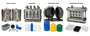
We support injection, blow, LSR, thermoforming, and rotational molding. When a part struggles in one process, we can compare it against another. Designs headed for plastic injection molding receive feedback on wall thickness, draft, gating, ejection, and tolerances.
Our quality systems are certified to ISO 9001:2015, AS9100 Rev D, and ISO 13485:2016.
It is used to adjust a part design before tooling so the part molds consistently. It reduces defects, tool rework, cycle time, and unnecessary tolerances that add cost.
It should happen after the 3D model is ready and before mold design begins. Changes at this stage cost far less than changes made after steel is cut.
Each resin shrinks and flows differently. Glass-filled and semi-crystalline resins can warp more. DFM feedback adjusts wall thickness, gating, and tolerances to suit the chosen material.
The core guidelines stay the same. Cleanroom parts add documentation, handling, and packaging considerations. Medical programs also need DFM decisions recorded under their quality system for design history purposes.
The design owner, usually the customer, decides which recommendations to accept. The molder advises on risk and cost. Documenting each decision keeps design records clear for sampling and audits.
What is design for manufacturability in plastic injection molding? It is the early review that makes a part moldable, repeatable, and cost-effective before tooling begins.
Keep these decision points in mind:
If you have a part that is nearing tooling, we are glad to review it and share our feedback. You can reach our engineering team here, call 951-354-0258, or visit us at 7575 Jurupa Ave, Riverside, CA 92504.